Single Board Relay Computer
Hacking the Verifone ZON Jr XL
Acoustic Delay Line Memory
Text Editor Performance Comparison
MPL
Delay Line MemoryDelay line memory always fascinated me. It is well known that early computers such as the UNIVAC-I used mercury acoustic delay line memory. Less well known is that the use of digital delay line memory continued well into the semiconductor era in the form of Torsional and Quartz delay line memories for calculators.Analog delay line memory also has had many uses over the years. One common use was for drop-out compensators in video tape recorders. As each video line was read from the video tape, a copy was stored in a delay line. If a drop-out was detected (indicated by the loss of the FM carrier) in a particular line, the signal from the previous line from the output of the delay line was substituted in its place to improve the look of the video. Another common use was in MTI (Motion Target Indicator) RADAR. In this case the signal recorded in a delay line from a previous ping was subtracted from the signal from the current ping to eliminate non-moving "clutter" and highlight anything which was moving. Build your own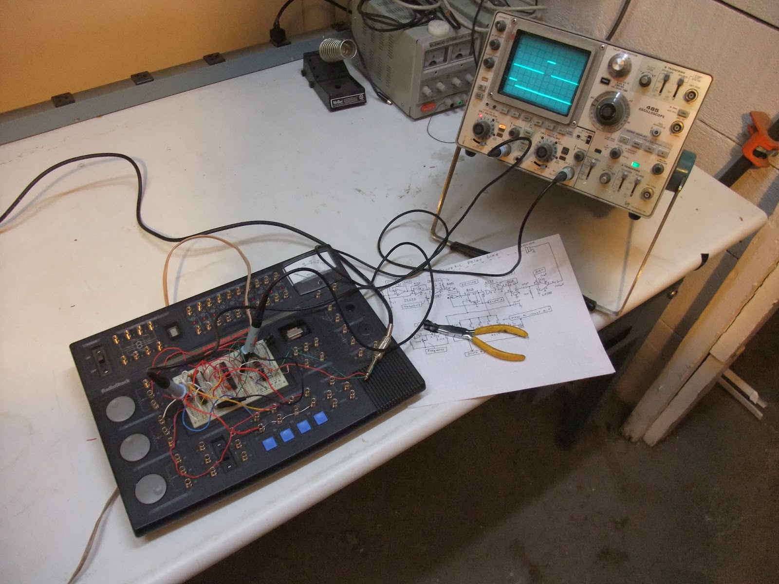 I thought it would be neat to make an acoustic digital delay line memory which operated at audio frequencies and used air as the delay media so that I could hear it operating. It turns out that Radio Shack's Electronics Learning Lab (with instructional guides written by Forrest Mims III) provides nearly all of the components necessary to build your own acoustic delay line memory. I used this kit, plus a speaker, a dynamic microphone and some long wires so that the speaker can be separated from the microphone by about 20 feet. Here is the schematic: 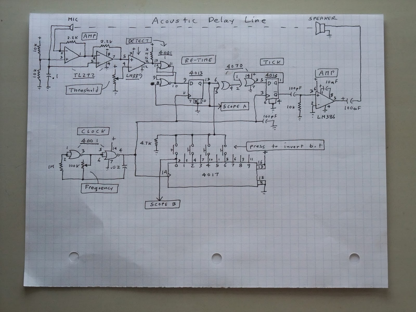
(click to enlarge)
Circuit DescriptionThe key component is the 4017 decade counter / decoder. This chip provides the frame timing and provides an easy way to consistently locate each bit in the delay line. A 4001-based RC oscillator provides the clock for the 4017 and the 4013 flip-flops. There are 10-bit times: two of them are in the 4013 flip-flop and the remaining 8 are in the air. The speed of sound is about 1100 ft / second, so 20 feet separation between microphone and speaker results in a delay of about 18 ms. 8 bits in 18 ms means that each bit should be about 2.25 ms, so the clock frequency should be about 444 Hz.The TL272 OP-AMP amplifies the signal from the microphone. The LM339 comparator detects the signal. The detection threshold can be adjusted with a potentiometer. When a signal is detected, a 4001-based set-reset flip-flop is set. A 4013 D-flip flop clocks in (or "re-times") the detected bit and also clears the set-reset flip-flop. A "bit injection" exclusive-OR gate is inserted at this point of the signal path. This allows bits to be injected into the memory. When a button is pressed, the bit at that specific time is inverted by this gate. A second exclusive-OR gate and a 4013 D flip-flop are set up as a toggle flip-flop. When the input is a 1, the flip-flop toggles. This is passed through an RC high-pass filter to the LM386 audio amplifier which is connected to the speaker. Whenever this flop-flop toggles a "tick" sound is emitted by the speaker. The polarity of the "tick" doesn't really matter since some ringing will be associated with the sound. It's one of the cycles of the ringing which is detected by the LM339. Here is the circuit built on the Electronics Learning Lab breadboard. The top knob controls the detection threshold. The bottom knob controls the bit-rate. The four blue buttons each invert a specific bit of the memory: 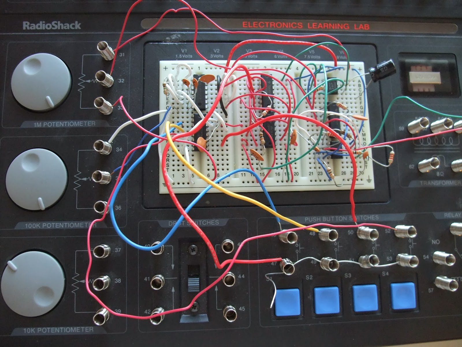 CalibrationTo calibrate and watch the circuit operating you really need an oscilloscope. I use an old Tektronix 485. One channel is connected to bit 0 of the 4017 as the "start of frame" pulse. The scope is set to trigger on this pulse and the time-base is set so that a bit more than a single frame fits across the screen. The other channel is connected to output of the re-timing flip-flop to watch for any captured bits.To calibrate the system break the path between the 4013 re-timing flip flop and the following bit injection exclusive-OR gate. Connect the input to the exclusive-OR gate to ground instead. Now turn on the circuit, hold down the button connected to bit 0 and watch the scope. Adjust the threshold so that you can just see a signal from the detected "tick" sounds. Now adjust the frequency so that the detected bit happens at the same time as the "start of frame" pulse. Calibration is now done, so connect the re-timing flip-flop back up to the exclusive-OR gate. Now the loop is closed and the circuit will automatically regenerate each detected bit. VideoHere is a video of the delay line memory operating. I set each bit in turn, and then clear them in the reverse order. The buttons make enough acoustic noise so that pressing them sometimes sets unrelated bits. For this reason it is probably better to place the microphone as far from the buttons as possible:Other ExperimentsCounterYou can make a counter out of the delay line memory by adding a carry flag (with another 4013 D flip-flop). Invert a bit if the carry flag is set (so feed the output of the carry flag into the signal injection exclusive-OR gate). Set the carry flag if the current bit is a 1 and the carry flag is also a 1 (so you need an AND gate).ModulationThe Electronics Learning Lab provides a 4046 phase locked loop chip. With the VCO and phase detector blocks in this chip it should be possible to use a better modulation method (perhaps FSK or PSK) and thereby get more reliable operation and higher bit density. |